PowerFlex 755 Manual PDF: A Comprehensive Guide
This comprehensive PDF guide details the PowerFlex 755 AC drive, offering versatile motor control, easy integration, and high performance for increased productivity.
The PowerFlex 755 is a robust AC drive designed to meet diverse global motor control needs. This drive excels in providing versatile performance, simplified integration into existing systems, and consistently high operational efficiency, ultimately boosting productivity across various industrial applications.
Available in a broad power range, initially from 7;5 to 250 kW (and now extending to 1500 kW/2000 Hp), the PowerFlex 755 caters to a wide spectrum of requirements. Rockwell Automation continually expands its capabilities, evidenced by recent power range extensions to 450kW/700 Hp. Its unique roll-in/out design simplifies installation, particularly in heavy-industrial settings. This manual provides a detailed overview for optimal utilization.
Key Features and Benefits
The PowerFlex 755 boasts several key features delivering significant benefits to users. Its broad power range (7.5 kW to 1500 kW/2000 Hp) accommodates diverse applications. The dual-port EtherNet/IP module facilitates seamless communication and integration within industrial networks.
Furthermore, the drive’s design prioritizes ease of installation, exemplified by the roll-in/out architecture for larger models. This translates to reduced downtime and quicker setup. By optimizing motor performance and enhancing system reliability, the PowerFlex 755 contributes to improved energy efficiency. This manual unlocks the drive’s hidden potential, offering insightful tips and tricks for maximizing its capabilities.
Power Range and Applications
The PowerFlex 755 AC drive offers a remarkably wide power range, starting at 7.5 kW and extending up to an impressive 1500 kW / 2000 Hp, covering a vast spectrum of industrial needs. This scalability makes it suitable for diverse applications, from basic motor control to complex, heavy-industrial processes.
Specifically, the extended power range caters to demanding applications requiring substantial horsepower. The drive’s versatility allows it to be implemented across numerous sectors, optimizing performance and efficiency. Modern industrial automation relies on VFDs like the PowerFlex 755 to improve energy use and system reliability, making it a crucial component in contemporary facilities.
Installation and Configuration
Proper installation involves unpacking, inspection, mounting, and wiring, ensuring correct connections and adherence to guidelines for optimal performance and safety.
Unpacking and Inspection
Upon receiving your PowerFlex 755 drive, carefully inspect the shipping container for any signs of damage during transit. Document any external damage immediately with the carrier. Once opened, verify the drive’s physical condition, checking for loose components or visible defects.
Compare the received unit against the packing list to ensure all components are present, including the drive itself, any optional modules (like EtherNet/IP adapters), and documentation.
Thoroughly examine the drive’s terminals and connectors for any damage or contamination. If any discrepancies or damage are found, do not attempt to install or operate the drive; contact Rockwell Automation support for assistance and guidance. Retain all packaging materials for potential return or claim purposes.
Mounting and Wiring Guidelines
Proper mounting is crucial for optimal PowerFlex 755 performance and longevity. Ensure the drive is installed in a clean, dry environment, free from excessive dust, moisture, and vibration. Mount the drive vertically on a suitable surface capable of supporting its weight – models range up to 450kW/700Hp and beyond, requiring robust support.
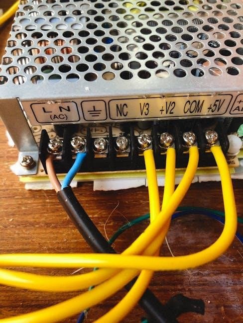
Maintain adequate spacing around the drive for proper ventilation, preventing overheating. Wiring should adhere to all applicable electrical codes and standards. Use appropriately sized conductors and ensure secure connections to all terminals.
Follow the wiring diagrams provided in the manual carefully, paying close attention to grounding requirements for safety and noise reduction. The unique roll in/out design of some models streamlines installation, but proper wiring remains paramount.
Control Wiring and Parameters
Effective control wiring and parameter configuration are essential for tailoring the PowerFlex 755 to specific applications. The drive supports various control methods, including digital and analog inputs, enabling flexible integration with PLCs and other automation systems.
Key parameters govern motor characteristics, acceleration/deceleration rates, and protection settings. Utilize the Human Interface Module (HIM) or embedded web server for parameter adjustments.
The dual-port EtherNet/IP module facilitates seamless communication for advanced control and monitoring. Careful parameter selection optimizes performance, enhances energy efficiency, and safeguards the motor and drive from potential faults. Refer to the manual for detailed parameter descriptions and recommended settings.
Operation and Monitoring
The PowerFlex 755 offers straightforward operation and comprehensive monitoring capabilities via the HIM, display, and communication networks for optimal control.
Basic Operation Procedures
Initiating operation with the PowerFlex 755 involves a systematic approach, beginning with verifying proper wiring and parameter settings. Ensure the drive receives adequate power and the motor is correctly connected. Utilize the Human Interface Module (HIM) to navigate the drive’s menu and confirm the desired speed and direction.
The drive’s control terminals accept start/stop signals, enabling remote operation. Carefully review the manual for specific wiring configurations. Before applying power, double-check all connections to prevent damage. Once powered, monitor the drive’s display for any fault indications.
Gradually increase the speed reference to observe motor performance and confirm proper operation. Always adhere to safety guidelines during commissioning and operation.
Drive Status and Display Information
The PowerFlex 755’s display provides crucial real-time information regarding its operational status. Key indicators include drive enabled/disabled, motor speed (in Hz or RPM), output frequency, and current draw. Fault codes are prominently displayed, accompanied by descriptive messages to aid in troubleshooting.
The Human Interface Module (HIM) allows for detailed monitoring of parameters like voltage, current, and temperature. Diagnostic screens offer insights into drive performance and potential issues. Understanding these displays is vital for efficient operation and proactive maintenance.
Regularly checking the display can prevent unexpected downtime and ensure optimal motor control. Refer to the manual for a complete explanation of all status indicators and error messages.
Using the Human Interface Module (HIM)
The PowerFlex 755’s Human Interface Module (HIM) provides a user-friendly interface for drive control and monitoring. Navigation is typically achieved through a keypad and display screen, allowing access to parameters, status information, and diagnostic tools.
The HIM enables operators to start, stop, and adjust drive settings, including speed, acceleration, and deceleration times. It also facilitates parameter configuration, allowing customization for specific application requirements.
Detailed troubleshooting information is accessible through the HIM, including fault code descriptions and potential solutions. The manual provides a comprehensive guide to HIM navigation and functionality, ensuring efficient operation and maintenance.

Troubleshooting and Fault Codes
This section details fault code categories, common issues, and solutions for the PowerFlex 755, aiding in quick diagnosis and drive restoration.
Understanding Fault Code Categories
The PowerFlex 755 utilizes a structured fault code system to quickly identify and address issues. These codes are broadly categorized to streamline troubleshooting. Major categories include Drive Faults, which indicate internal hardware or software problems requiring attention. Motor Faults signal issues with the connected motor, like overloads or phase loss.
Control Wiring Faults pinpoint problems with external control signals, while Power Supply Faults relate to input power irregularities. Communication Faults highlight issues with network connections, such as EtherNet/IP. Understanding these categories allows technicians to efficiently narrow down the source of the problem, reducing downtime and improving system reliability. The manual provides detailed explanations for each category and associated codes.
Common Fault Codes and Solutions
The PowerFlex 755 manual details numerous fault codes, but some occur more frequently. Fault Code 4, “Drive Disabled,” often requires checking control wiring or parameter settings. Code 5, “Overcurrent,” indicates excessive motor current, potentially due to overload or wiring issues. Fault 8, “Overvoltage,” suggests a problem with the input power supply.
Code 10, “Under Voltage,” similarly points to power supply problems. Solutions often involve verifying wiring connections, checking motor load, and confirming correct parameter configurations. The manual provides specific troubleshooting steps for each code, including recommended actions and potential causes. Regularly reviewing these common faults can significantly reduce diagnostic time and improve uptime.
Resetting the Drive After a Fault
The PowerFlex 755 manual outlines several methods for resetting the drive following a fault condition. A simple reset can often be achieved by acknowledging the fault via the Human Interface Module (HIM). However, for persistent faults, a complete power cycle – disconnecting and reconnecting the AC power supply – may be necessary;
Before resetting, always address the root cause of the fault to prevent recurrence; The manual emphasizes verifying the fault condition is cleared before attempting a restart. Incorrect resets can lead to further issues. Refer to the specific fault code documentation within the manual for tailored reset procedures and safety precautions. Proper resetting ensures safe and reliable operation.
Advanced Features
The PowerFlex 755 manual details advanced capabilities like EtherNet/IP communication, specialized parameter configurations, and the functionality of the embedded web server.
EtherNet/IP Communication Setup

Establishing EtherNet/IP communication with the PowerFlex 755 is thoroughly covered in the manual, detailing setup procedures for seamless integration into industrial networks. The guide explains configuring the drive’s embedded EtherNet/IP adapter, including IP address assignment and network parameter configuration.
It provides step-by-step instructions for defining connections, configuring explicit messaging, and utilizing the drive’s object model for data exchange. The manual emphasizes the dual-port EtherNet/IP module availability for enhanced connectivity and redundancy. Troubleshooting tips are included to address common communication issues, ensuring reliable data transfer between the drive and control systems. Detailed examples and diagrams illustrate the process, making setup accessible for various skill levels.
Parameter Configuration for Specific Applications
The PowerFlex 755 manual PDF provides extensive guidance on tailoring drive parameters to diverse applications. It details how to optimize performance for various motor control needs, including constant torque, variable torque, and constant power applications.
Specific parameter adjustments for heavy-industrial uses, leveraging the extended power range up to 1500 kW/2,000 Hp, are explained. The manual covers configuring parameters for precise speed control, acceleration/deceleration profiles, and motor protection features. It also includes application-specific examples and troubleshooting advice, helping users fine-tune the drive for optimal efficiency and reliability. Understanding these configurations unlocks the drive’s full potential for specialized industrial processes.
Using the Embedded Web Server
The PowerFlex 755 manual PDF thoroughly explains utilizing the drive’s integrated web server for convenient access and control. This feature allows for remote monitoring, parameter adjustments, and diagnostics via a standard web browser.
The manual details the setup process, including IP address configuration and security considerations. Users can leverage the web server for real-time drive status updates, fault code analysis, and data logging. It also outlines how to upload and download parameter files, simplifying drive configuration and backup procedures. The dual-port EtherNet/IP module enhances connectivity, enabling seamless integration into existing industrial networks for efficient remote management.
Safety Considerations
The PowerFlex 755 manual PDF emphasizes strict adherence to electrical and mechanical safety guidelines, including emergency stop procedures, for safe operation.
Electrical Safety Guidelines
The PowerFlex 755 manual PDF strongly advises qualified personnel handle all electrical connections and maintenance. Always disconnect power before working on the drive or connected equipment, verifying zero voltage with appropriate testing devices.
Proper grounding is crucial to prevent electrical shock and equipment damage; follow the manual’s grounding instructions meticulously.
Ensure all wiring complies with local and national electrical codes. Avoid using damaged cables or connectors. The manual details specific voltage and current ratings; exceeding these limits can create hazards.
Regularly inspect wiring for wear and tear. Always use appropriate personal protective equipment (PPE), including insulated gloves and eye protection, when working with electrical components.
Mechanical Safety Precautions
The PowerFlex 755 manual PDF emphasizes secure mounting of the drive to a suitable surface, capable of withstanding its weight and potential vibrations. Ensure adequate ventilation to prevent overheating, maintaining clearances as specified in the documentation.
Avoid installing the drive in areas exposed to excessive dust, moisture, or corrosive substances.
When handling the drive, use appropriate lifting techniques and equipment to prevent injury. Inspect the drive for any physical damage before installation and operation.
Properly secure all wiring and cabling to prevent strain or disconnection. The manual details specific mounting orientations; adhere to these guidelines for optimal performance and safety.
Emergency Stop Procedures
The PowerFlex 755 manual PDF clearly outlines critical emergency stop procedures for immediate shutdown in unsafe conditions. Implement a dedicated emergency stop circuit, wired directly to the drive’s control terminals, bypassing normal control logic.
Ensure the emergency stop circuit is independent and reliable, utilizing appropriately rated components.
Upon activation of the emergency stop, the drive should immediately remove power from the motor, bringing it to a controlled stop – or a rapid stop, depending on the application’s safety requirements.
Regularly test the emergency stop circuit to verify its functionality. The manual provides detailed wiring diagrams and configuration guidance for implementing a robust emergency stop system.


About the author